Input Context
Load Input Snapshot
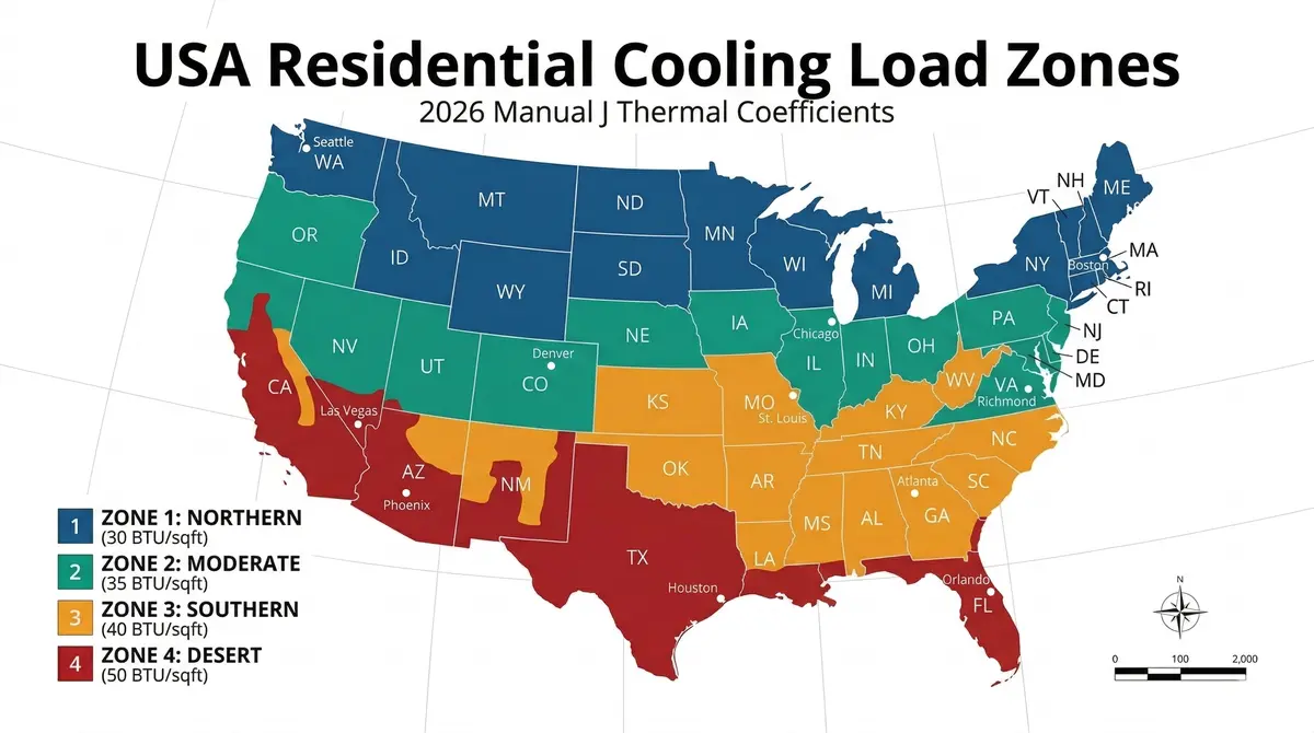
Review the active floor area, structure age, ZIP/climate baseline, ceiling height, and duct-loss setting before generating results. The screening output still requires field verification before equipment, duct, or electrical decisions.
HVAC Reference Snapshot
2026 Manual J Thermal Reference Summary
Whole-House Load Screening /
Reference Method
Manual J
Baseline
Load Screening Hierarchy
Design Temps
Result Review Status
Result Status
System Layout Review
:
Load Screening Output
Cooling load, heating load, and electrical nameplate context are shown separately.
Cooling tons reference and airflow screening are based on cooling load only. Airflow follows the selected CFM/ton bias. Heating load is shown as a separate thermal screening value. Electrical load requires equipment nameplate data.
Cooling Load Screening
Cooling BTU
Sensible BTU
Latent BTU
Cooling tons reference
Tons
Multi-system warning: exceeds 5.0 tons. Do not plan this as one residential unitary system.
Cooling airflow reference
CFM
Airflow reference follows the cooling load only and uses CFM/ton (). Actual blower setup depends on equipment tables, duct static pressure, humidity target, and commissioning.
Heating Load Screening
Heating BTU
Heating fuel/equipment electrical load
Not determined
Heating type: . Thermal heating BTU does not identify gas, heat pump, dual-fuel, blower, or electric heat-kit electrical load.
Auxiliary Heat Circuit Warning: Heating BTU is the structure heat-loss screen only. Do not size electric heat strips from the full load or from an assumed heat-pump delta. Supplemental heat circuits require selected equipment performance at winter design temperature, heat-pump balance point, auxiliary staging, heat-kit kW, MCA/MOCP, and manufacturer instructions.
Electrical Nameplate Context
Nameplate required
Topology: • Indoor power: • Layout status:
Do not use BTU-derived VA for NEC panel or service sizing.
Wire sizing requires equipment MCA/MOCP. Do not use BTU, tonnage, or airflow values for NEC 440 branch-circuit sizing.
MOCP Warning: nominal tonnage cannot set breaker size. Inverter and variable-speed equipment may require a lower max breaker than rule-of-thumb expectations.
Field Output Snapshot
Thermal load, airflow reference, and electrical nameplate status stay separated.
Cooling tons and airflow are screening references only. Electrical branch-circuit decisions remain blocked until topology is selected and actual MCA/MOCP or heat-kit kW is entered.
Cooling tons reference
tons
Not MCA, MOCP, breaker size, wire size, RLA, or LRA.
Airflow reference
CFM
CFM/ton • .
Glazing exposure
Solar gain modifier used only for screening.
System layout
Electrical handoff
Cooling BTU
Cooling thermal load screen. Not electrical load.
Heating BTU
Separate thermal review. Do not convert to heat-kit kW.
Project Size
Sq.Ft
Screening Snapshot
Climate Source:
Humidity:
Region Bias:
Elevation:
Airflow Bias:
Glazing Exposure:
Heating Type:
Indoor Power:
Heating Load Screening
Heating Review
Indoor: 72°F •
Heating fuel/equipment electrical load
Not determined — verify actual fuel type, blower load, and electric heat-kit kW from equipment data.
Resistive Heat Warning: Do not divide thermal BTU by 3,412 to size heat strips. Heating equipment type, balance point, staging, heat-kit kW, and MCA/MOCP must come from equipment data.
Cooling Load Breakdown
Review the cooling load components used in this screening result.
Sensible Load
BTU
Latent Load
BTU
Total Cooling
BTU
Sensible Heat Ratio
Sensible share of the current total cooling load.
SHR
Detailed Analysis
Expand for airflow interpretation and equipment-screening context.
Airflow Interpretation
Airflow reference
CFM/ton
Equipment Screening Context
Tons reference
Pre-screening caution
Manual S Equipment Screening Baseline
Cooling output formatted as a Manual S equipment screening starting point.
Cooling tons reference range
– Tons
Cooling baseline
Candidate equipment tonnage
Optional field-use cross-check for comparing the candidate equipment size against the cooling baseline.
Manual S note
Use this range as the starting equipment screening bracket, then verify actual capacity, latent behavior, and airflow against the final equipment match.
System Viability Review
Display-only performance-risk review before final equipment screening.
Sanity Validation
Display-only plausibility review based on current inputs and calculated load.
Manual J Screening Data Ready
Design Temps: • 75°F Indoor cooling baseline • 72°F Indoor heating baseline
Equipment Data Review
Review AHRI / OEM equipment data before hardware decisions
Cooling tons reference is not a shopping, single-system, wire-sizing, or breaker-sizing instruction.
Manual J Load Screening Reference.
Field Requirement: AHRI matching, OEM capacity tables, blower data, and equipment nameplate values control final equipment and electrical decisions. Tonnage and airflow references are screening values only.
Manual J Load Screening Field Reference
Manual J load screening boundary
Use this result for early load review. Do not use it as a final Manual J report or equipment approval.
The Manual J calculation tool estimates cooling BTU, sensible and latent cooling load, cooling tons reference, airflow reference, and heating load review from field inputs. Airflow bias, glazing exposure, and heating equipment type are explicit screening assumptions. Electrical handoff remains blocked until actual equipment MCA/MOCP or heat-kit kW is entered.
Cooling Review
Cooling tons reference and airflow reference are based on the cooling load only, including sensible and latent load split and the selected CFM/ton airflow bias.
Heating Review
Heating load is reviewed separately and may be the larger thermal load, but it does not set cooling tons, airflow, electric heat-kit kW, or branch-circuit sizing.
Electrical Boundary
Electrical service, feeder, disconnect, breaker, or conductor sizing requires actual equipment nameplate or submittal data such as MCA, MOCP, compressor data, blower load, and heat-kit kW. Thermal BTU, nominal tonnage, and airflow references stay blocked from electrical handoff.
Tool Scope
What the Manual J Calculation Tool Does
This calculator gives field technicians a rapid whole-house load screening reference before final room-by-room Manual J, Manual S equipment screening, Manual D duct design, or electrical nameplate coordination.
Whole-house block load
Screens cooling and heating BTU using envelope inputs, regional design-temperature assumptions, infiltration, internal gains, directional glazing, solar gain, duct-loss assumptions, and structure-age defaults.
Jobsite diagnostic starting point
Helps evaluate existing equipment size, comfort complaints, and homeowner expectations before a full room-by-room Manual J, equipment match, or duct review is performed.
Cooling, heating, and airflow separation
Keeps cooling BTU, heating BTU, cooling tons reference, and airflow screening reference separated so heating load does not drive cooling tons or duct airflow.
Climate airflow bias
Allows latent/humid, standard, or dry/sensible airflow assumptions instead of forcing every job into a fixed 400 CFM per ton reference.
Glazing exposure adjustment
Adjusts directional solar gain for heavy shade, standard exposure, or high exposure so shaded and exposed homes are not treated the same.
Single-system feasibility flag
Flags cooling loads above 5.0 tons so the result is reviewed for zoning, multiple systems, equipment layout, and separate downstream coordination.
Field Checks Before Trusting The Result
Confirm the field inputs that can move the load.
Verify ZIP or climate baseline against the local outdoor design temperature for the project location.
Confirm conditioned floor area, ceiling height, structure age, and envelope condition before trusting BTU density.
Review window area, orientation, and the Glazing Exposure setting. Exterior shade, overhangs, limited shade, or west/south exposure can move the cooling load.
Confirm duct location and delivery-loss assumptions before using airflow or equipment screening values.
Account for internal gains from occupants, appliances, electronics, kitchens, laundry, and other field conditions.
Cross-check equipment candidates with AHRI/OEM performance data before treating tonnage as acceptable.
Nameplate Required
Do not convert thermal BTU into NEC service or panel load.
HVAC electrical coordination must use actual equipment data. Use MCA/MOCP, compressor information, blower load, accessory data, and electric heat kit kW where applicable before continuing to panel or service calculations.
Safe handoff rule
The electrical handoff carries context only. It should not auto-fill VA from this thermal load screen.
What This Result Does Not Prove
What this result does not verify.
A Manual J load screen is useful for early review, but it is not the same as final project documentation or verified equipment performance.
- It does not prove a final Manual J report is complete.
- It does not approve a Manual S equipment match.
- It does not complete Manual D duct sizing or static pressure review.
- It does not size NEC service, panel, feeder, branch circuit, MCA, or MOCP values.
- It does not determine indoor unit voltage, 120V vs. 240V rough-in, neutral requirements, or package vs. split circuit layout.
- It does not account for branch-circuit distance or voltage drop; long equipment runs require a separate voltage-drop check using actual MCA, voltage, conductor material, and run length.
- It does not determine ambient-temperature conductor derating, mini-split / VRF indoor wiring topology, or noncoincident heating/cooling treatment for NEC service-load calculations.
- It does not replace AHRI/OEM expanded performance data.
- It does not override local code requirements, manufacturer instructions, or AHJ review.
Manual J Load Screening Workflow
This utility builds a Manual J-based screening baseline from conditioned area, structure age, window direction, ZIP/climate context, infiltration assumptions, internal gains, and duct-loss settings.
01. Establish Thermal Baseline
Enter net conditioned area, ceiling height, and structure age to set baseline envelope and infiltration assumptions.
02. Set Regional Climate Context
Use ZIP-prefix climate data when matched, or a climate-zone baseline when ZIP context is unavailable. Verify local conditions before final decisions.
03. Review Directional Glazing
Check window area by orientation so solar exposure is represented before using the cooling load or airflow reference.
04. Account For Internal Gains
Review occupants, appliance load, kitchen/laundry intensity, and high-demand electronics before trusting the load direction.
05. Carry Safe Context Forward
Use cooling load values for Manual S equipment screening, cooling airflow for Manual D duct design, and nameplate data for electrical review.
How Results are Determined
How the load screen is calculated.
01. Climate context
ZIP-prefix or climate-zone baseline sets summer and winter temperature context; unmatched ZIPs remain review-required.
02. Envelope assumptions
Structure age, R-value defaults, glass assumptions, ACH, glazing exposure, and advanced overrides shape the envelope and solar load screen.
03. Cooling screen
Cooling load combines envelope transfer, directional glazing with the selected exposure modifier, internal gains, infiltration, altitude, and duct-loss settings.
04. Heating review
Heating load reviews envelope loss, glass loss, infiltration, altitude, winter temperature context, and selected heating equipment type separately.
05. Output boundary
Cooling tons reference comes from cooling load only. Airflow reference uses the selected CFM/ton bias. Electrical handoff remains blocked unless actual equipment MCA/MOCP or heat-kit kW is entered.
HVAC Workflow Bridge
Manual J Load Screening → Manual S Equipment Screening → Manual D Duct Design
Cooling and heating reference values start the HVAC review. Equipment screening should use cooling load values, duct design should use the selected airflow reference, and electrical review should use entered nameplate data only.
Current Page
Manual J Load Screening
Establish cooling, heating, airflow, glazing exposure, and heating equipment context from field inputs.
Equipment Review
Screen equipment using cooling BTU, sensible load, latent load, and cooling tons reference in Manual S Equipment Screening.
Duct Review
Size ductwork using the selected cooling airflow reference in Manual D Duct Design.
Source Alignment Review
Manual J screening reference context.
This calculator uses Manual J-style residential load-screening concepts with ASHRAE-informed temperature context, ZIP-prefix climate baselines, structure-age envelope defaults, directional glazing inputs, glazing exposure modifier, internal gains, infiltration assumptions, selected airflow bias, heating equipment context, and duct-loss adjustments.
Review source notes on the Code Citations & Verification page. Public references: ACCA Manual J and ASHRAE Climatic Design Information.
Electrical service or panel sizing should continue through the Residential Load Calculator only when actual MCA/MOCP or heat-kit kW has been entered. Without nameplate data, this link returns to the electrical data gate instead of passing thermal load values.