TradeHub Tools Field Reference Chart
Ampacity Derating Multiplier Chart
Source scope: NEC 310.15-style current-carrying conductor adjustment and ambient correction reference. Field reference only; not an official NEC table replacement.
Page URL: https://www.tradehub.tools/resources/electrical/field-tables/ampacity-derating-chart
Primary Field Chart
Ampacity Derating Multiplier Chart
Use these field multipliers to screen the two common derating steps: current-carrying conductor adjustment and ambient temperature correction. This page does not approve final conductor size; terminal temperature limits, conductor material, insulation rating, wiring method, and OCPD rules still need review.
Current-Carrying Conductor Adjustment
| CCC Count | Adjustment Factor | Field Note |
|---|---|---|
| 1–3 | 100% | Baseline count range before the more-than-three adjustment applies. |
| 4–6 | 80% | Common small bundle adjustment. |
| 7–9 | 70% | Multiple circuit sets may land here. |
| 10–20 | 50% | Heavy bundling; calculator review recommended. |
| 21–30 | 45% | Large conductor-count adjustment. |
| 31–40 | 40% | High-density conductor grouping. |
| 41+ | 35% | Very high conductor count; verify before relying on chart. |
Ambient Temperature Correction Factors
| Ambient °F | Ambient °C | 60°C Factor | 75°C Factor | 90°C Factor |
|---|---|---|---|---|
| 50°F or less | 10°C or less | 1.29 | 1.20 | 1.15 |
| 51–59°F | 11–15°C | 1.22 | 1.15 | 1.12 |
| 60–68°F | 16–20°C | 1.15 | 1.11 | 1.08 |
| 69–77°F | 21–25°C | 1.08 | 1.05 | 1.04 |
| 78–86°F | 26–30°C | 1.00 | 1.00 | 1.00 |
| 87–95°F | 31–35°C | 0.91 | 0.94 | 0.96 |
| 96–104°F | 36–40°C | 0.82 | 0.88 | 0.91 |
| 105–113°F | 41–45°C | 0.71 | 0.82 | 0.87 |
| 114–122°F | 46–50°C | 0.58 | 0.75 | 0.82 |
| 123–131°F | 51–55°C | 0.41 | 0.67 | 0.76 |
| 132–140°F | 56–60°C | — | 0.58 | 0.71 |
| 141–149°F | 61–65°C | — | 0.47 | 0.65 |
| 150–158°F | 66–70°C | — | 0.33 | 0.58 |
| 159–167°F | 71–75°C | — | — | 0.50 |
| 168–176°F | 76–80°C | — | — | 0.41 |
| 177–185°F | 81–85°C | — | — | 0.29 |
Field note: these multiplier tables are quick references. Use the correction column that matches the conductor insulation temperature rating when permitted, and the final result still must stay within the applicable terminal temperature limit.
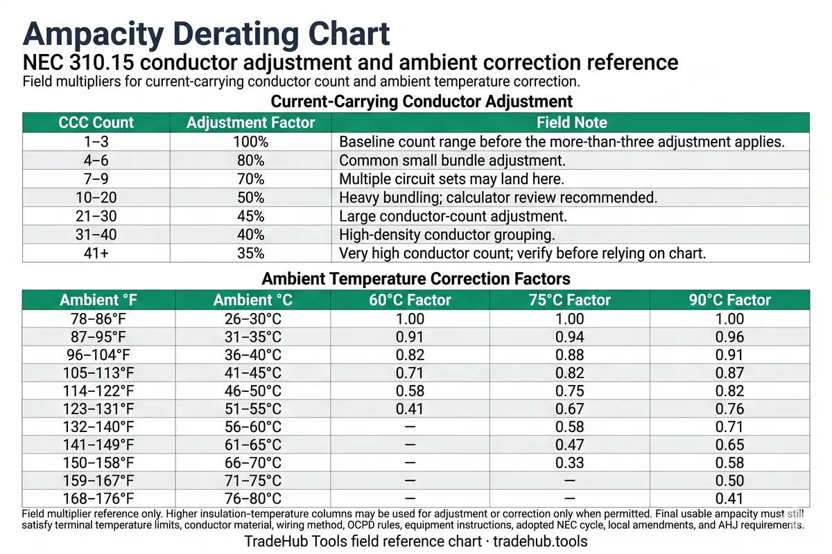
Calculator-use note: use the Ampacity Calculator when current-carrying conductor count, ambient temperature, insulation rating, terminal rating, wiring method, conductor material, or OCPD conditions stack together.
TradeHub Tools field reference only. Verify against the adopted NEC cycle, conductor markings, product data, site conditions, and local inspection authority.
Scope Boundary
When This Chart Applies
- Use for baseline derating checks: This chart helps screen current-carrying conductor adjustment and ambient temperature correction factors for 60°C, 75°C, and 90°C conductor ratings before using a full ampacity workflow.
- Do not treat it as final conductor approval: Final usable ampacity still depends on terminal temperature limits, conductor material, insulation rating, wiring method, cable assembly rules, OCPD limits, and project conditions.
- Watch stacked conditions: If both conductor count and ambient temperature apply, the factors must be stacked correctly before comparing against final limits.
Calculator Handoff
When to Use the Ampacity Calculator
Use the calculator when conductor count, ambient temperature, insulation rating, terminal rating, conductor material, wiring method, or small-conductor rules affect the final result. The calculator keeps the multiplier steps tied to the final usable ampacity boundary instead of leaving the result as a loose chart lookup.
Related Code References
NEC 310.16 Ampacity Table
Base conductor ampacity reference
NEC 310.15(C)(1) Adjustment
Current-carrying conductor factors
NEC 310.15(B)(1) Temperature
Ambient correction context
NEC 110.14(C) Terminal Temp
Final ampacity cap boundary
NEC 334.80 NM Cable Ampacity
NM-B correction and 60°C cap
NEC 240.4(D) Small Conductor
Small-conductor OCPD limits
Source Scope
Source Alignment and Use Scope
This TradeHub field reference is based on NEC 310.15-style ampacity adjustment and correction concepts for screening and planning only. It does not reproduce the full NEC ampacity table set and does not replace the adopted code, conductor markings, product data, site conditions, engineering review, or local inspection authority. Review the TradeHub Code Citation & Source Log for source alignment records and the TradeHub Methodology page for how field references are scoped.
Common Questions
Ampacity Derating FAQ
Is ampacity derating the same as wire sizing?
No. Ampacity derating adjusts allowable conductor ampacity for field conditions. Final wire sizing still needs terminal rating, conductor material, insulation, OCPD, wiring method, and load-basis review.
Can I use only one derating multiplier?
Not always. A raceway may need both current-carrying conductor adjustment and ambient temperature correction before the result is compared against final limits.
Can I always use a higher temperature-rating column for derating?
No. Higher insulation-temperature columns may be used for adjustment or correction only when permitted by the conductor and installation conditions, and the final usable ampacity still cannot exceed the applicable terminal temperature limit.